The Problem
We wanted to connect all our networks, Site Kivu, Site Cleveland, and Site Washington, together to run bigger, wide-scale projects across multiple WAN connections and sites. The goal wasn’t primarily security; it was about achieving high availability, clustering, and being able to manage and test multiple labs as if they were part of a single, unified network. To address the challenges of NAT, dynamic public IP addresses, and SOHO router limitations, we opted for a hub-and-spoke topology. This allowed all remote sites to initiate connections to a central hub with a public IP, simplifying routing, scaling to multiple sites, and keeping the network manageable.
What we used (Pfsense, Opnsense, StrongSwan) and why?
OPNsense (Two Sites)
Two of the three sites ran OPNsense, mainly because that’s what those labs were already using. It provided the necessary IPsec, routing, and firewall features needed for the design without requiring anything unusual or custom.
pfSense (One Site)
One site intentionally ran pfSense. This wasn’t because it was better or worse; it was to prove the design wasn’t platform-dependent. If the topology worked with both pfSense and OPNsense, then the architecture itself was solid.
StrongSwan (Hub)
The StrongSwan system did not behave like the other sites. Instead, it acted as the central hub to which all remote networks connected. It ran on a VPS with a stable public IP, which served as the fixed anchor point for every IPsec tunnel in the environment.
Each pfSense and OPNsense site initiated an outbound IPsec tunnel to the StrongSwan hub. This design allowed all remote sites to connect successfully, even though they were behind NAT and using dynamic public IP addresses, without requiring port forwarding or special ISP configuration.
Running StrongSwan at the hub gave us full control over IKEv2 and, more importantly, inter-tunnel routing. Unlike typical firewall-to-firewall VPNs that terminate traffic at the tunnel endpoint, the StrongSwan hub could receive traffic from one site and forward it to another. This capability is what transformed multiple independent site-to-site VPNs into a single, routed multi-site network.
Because the hub had a fixed public IP and handled all routing between tunnels, the architecture scaled cleanly while remaining reliable and predictable, even as spoke sites changed public addresses.
More Details on what these are
PfSense
An open-source firewall and routing platform based on FreeBSD that provides firewalling, routing, NAT, and VPN services.
OPNsense
An open-source FreeBSD-based firewall platform offering routing, firewalling, and VPN functionality through a web interface.
StrongSwan
An open-source IPsec implementation for Linux that handles IKE key exchange and IPsec tunnel management.
Overview of the Hub-and-Spoke Topology
We went with a hub-and-spoke design where every remote site connects to a single central hub. In our case, that hub is a VPS with a public IP running StrongSwan. Each site brings up an IPsec tunnel from its WAN interface to the hub over the Internet.
Because the tunnel is always initiated by the remote site, this works even if the site is behind a NAT or a basic SOHO router. No inbound port forwarding is required, which was a hard limitation for some of our setups.
When the tunnel comes up, IKE Phase 1 handles authentication and key exchange using a pre-shared key. Once that’s done, IKE Phase 2 is where we define what actually goes through the tunnel. This is where we specify which local networks should be reachable and which remote networks they’re allowed to talk to.
Only traffic that matches those networks is encrypted and sent through the tunnel to the hub. Everything else follows the normal default route out to the internet. From there, the hub routes traffic between sites as needed, effectively tying multiple independent labs together without breaking normal WAN access.
This setup lets us treat separate networks like one larger environment while working around NAT, changing public IPs, and the limitations of consumer networking gear.
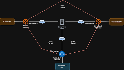
Fig 1: logical-network-diagram-example
Pros & Cons
Pros
- Works with NATed Sites: Remote sites can initiate tunnels to the hub without needing port forwarding.
- Handles Dynamic IPs: Even if spokes’ public IPs change, the hub remains a stable point of connection.
- Centralized Routing: All inter-site traffic flows through a single hub, simplifying management.
- Scalable: Adding new sites only requires creating a tunnel to the hub; no need for complex mesh setups.
Cons
Hub as a Single Point of Failure:
If the central hub becomes unavailable, all inter-site communication is interrupted.
Mitigation: Deploy a secondary hub with a public IP and configure backup tunnels from each site to provide redundancy and failover.
Potential Performance Bottleneck:
Because all inter-site traffic is routed through the hub, high traffic volumes or additional sites can strain hub resources and reduce throughput.
Mitigation: Scale the hub vertically by increasing CPU cores, memory, and disk performance (preferably SSD over HDD), or migrate to a higher-performance VPS as traffic demands grow.
Limited Direct Site-to-Site Traffic:
Spoke sites cannot initiate VPN tunnels directly to each other; all inter-site traffic must traverse the central hub.
Mitigation: If direct site-to-site connectivity is required, place pfSense or OPNsense directly on the WAN edge with a public IP address. This allows sites to establish direct VPN tunnels with each other, bypassing the hub and eliminating the dependency on centralized routing.
Technical implementation
The Hub: Ubuntu VPS with StrongSwan
The core of the network is an Ubuntu VPS running StrongSwan. It allows each home lab to communicate not only with the VPS but also with every other homelab in the mesh.
The key to making this work without complex routing protocols was the traffic selector config in ipsec.conf. By defining a list of subnets in the “leftsubnet” parameter, we instructed the VPS to encrypt traffic destined for any participating lab, not just the VPS itself.
StrongSwan Config: We all added our own connection to the ipsec.conf file. Below is a snippet of what one of ours would look like:
conn HomeLab-Peer
    # The Public IP of the VPS
    left=67.x.x.x
    leftid=67.x.x.x
    # All reachable subnets of the other routers.
    leftsubnet=192.168.255.9/32, 10.0.3.0/24, 10.200.0.0/24

    # Dynamic Remote (Handles dynamic home IPs)
    right=%any
    rightid=%any
    rightsubnet=172.16.1.0/24

    # Security
    keyexchange=ikev2
    authby=psk
    auto=add
Interface Config: To support policy-based IPsec on the StrongSwan hub, we did not rely on dummy or loopback interfaces. Instead, all participating site networks were explicitly defined within the IPsec configuration itself using traffic selectors.
By specifying each remote network directly in the VPN configuration, the VPS was able to correctly match outbound traffic against the appropriate IPsec policies. Any packet destined for a defined remote subnet was automatically selected for encryption and sent through the correct tunnel.
This approach ensured that traffic was “signed” and encrypted using the proper IPsec policies without requiring additional virtual interfaces or complex routing workarounds. It kept the configuration simpler, more transparent, and easier to maintain as new sites and subnets were added.
Configuration of VPS Servers (Ubuntu 22.04.5 LTS [Jammy Jellyfish]).
Step 1: Install strongSwan
# Update package lists
sudo apt update

# Install strongSwan
sudo apt install strongswan strongswan-pki libcharon-extra-plugins -y

# Verify installation
ipsec --version
Step 2: Generate Pre-Shared Key
# Generate a strong PSK
openssl rand -base64 32
Save this PSK securely - you'll need it for both Ubuntu and OPNsense.
Example output: cxgchVjKbCfj38tiv+4FX3X8a9MmJI1UUJO7a+f7...
Step 3: Configure IPsec Connection
Edit /etc/ipsec.conf:
sudo nano /etc/ipsec.conf
Add this configuration:
config setup
    uniqueids=never
    charondebug="ike 2, knl 2, cfg 2, net 2, esp 2"

conn OpnSenseRene
    left=Public ip of Hub
    leftid=Public ip of Hub
        leftsubnet=Other Spoke Subnets (Example : 10.0.3.0/24,172.16.1.0/24)
        right=Public ip of Spoke (Doesn’t matter if not static because of MOBIKE)
    rightid=%any
    rightsubnet=Your Spoke Subnet
    mark=1002
    auto=start
    keyexchange=ikev2
    ike=aes256-sha256-modp2048
    esp=aes256-sha256-modp2048
    dpdaction=restart
    dpddelay=30s
    dpdtimeout=120s
    authby=psk
    ikelifetime=24h
    keylife=1h
Configuration Explanation:
- left: VPS public IP
- leftsubnet: VPS tunnel endpoint IP
- right: OPNsense public IP (ISP router's WAN IP)
- rightsubnet: OPNsense LAN network
- mark=1002: IPsec mark for policy routing
- auto=start: Automatically start tunnel on boot
Step 4: Configure Pre-Shared Key
Edit /etc/ipsec.secrets:
sudo nano /etc/ipsec.secrets
Add this line (replace with your actual PSK):
67.217.242.202 146.135.14.64 : PSK "YOUR_GENERATED_PSK_HERE"
Security: Ensure proper file permissions:
sudo chmod 600 /etc/ipsec.secrets
sudo chown root:root /etc/ipsec.secrets
Useful Commands Reference
strongSwan status: sudo ipsec statusall
XFRM policies: sudo ip xfrm policy show
XFRM states: sudo ip xfrm state show
Packet capture: sudo tcpdump -i ens6 -n esp or udp port 4500
The spokes: OPNsense and pfSense
On the client side, we either set up pfSense or OPNsense. We avoided the complexity of BGP or OSPF by utilizing multiple phase 2 entries. A single IPsec Phase 1 connection to the hub carries multiple “Child SAs”, one for each destination in the network.
IPsec Phase 1 Config: We configured the algorithm, IKE version, the remote address (Hub Public IP), and DPD.
IPsec Authentication Config: We set up a pre-shared key as our authentication for our tunnels.
Phase 2 Config (or children in OPNsense): We each created multiple phase 2 tunnels. One to connect to the VPS as well as one for each remote homelab connection. For example, here were the following connections I used:
- Tunnel to hub: Local - 172.16.x.x > Remote - 192.168.255.x
- Tunnel to friend a: Local - 172.16.x.x > Remote - 10.0.3.x/24
- Tunnel to friend b: Local - 172.16.x.x > Remote - 10.200.x.x/24
This setup creates a “full mesh” capability where *sense encrypts traffic destined for a friend’s lab and tunnels it to the hub, while sending normal internet traffic out the local ISP connection.
IPsec Configuration in OPNsense
Configuring Phase 1 (Connection)
Navigate to VPN > IPsec > Connections.
Click the “+” button to add a new connection.
Configure Phase 1 (The Connection)
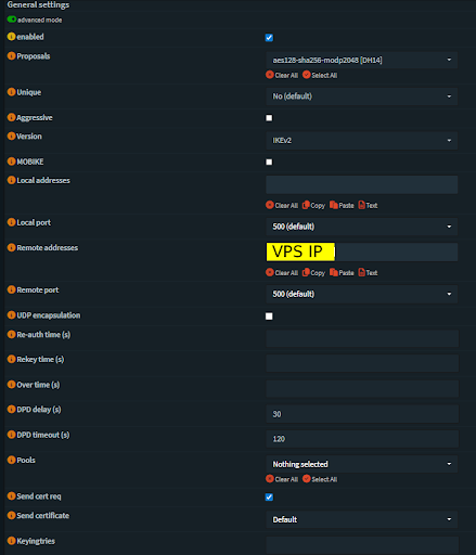
Fig 2: OPNsense IPsec Connection Configuration
Configuring Local and Remote Authentication:
Navigate to VPN > IPsec > Pre-Shared Keys and create a new key
Fill in the following:
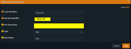
Fig 3: OPNsense Pre-Shared Key Configuration
Now go back to VPN > IPsec > Connections and edit your connection.
Scroll down to Local Authentication and click the “+” button.
Fill in the information but make sure your Id is the local identifier of your pre-shared key.
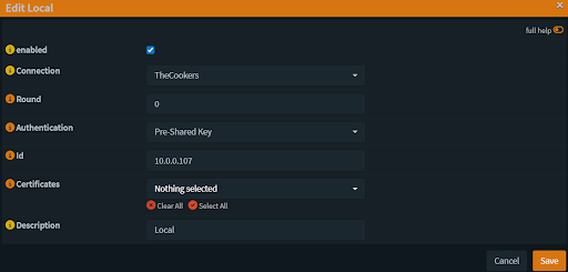
Fig 4: OPNsense IPsec Local Authentication Configuration
Do the same thing but for the remote authentication. Set the id to the public IP of the VPS.
Children Configuration:
Click the “+” button under Children and configure it. This is Phase 2 of the connection. You will need one child per homelab network and one for the VPS connection.
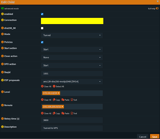
Fig 5: OPNsense Child SA Configuration
Make your local IP your LAN address.
Make your remote IP the VPS dummy address.
Check the Status
Navigate to VPN > IPsec > Status Overview
You should see all of your remote network connections under Phase 2 with Phase 1 being connected to the public IP of the VPS.
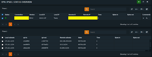
Fig 6: OPNsense IPsec Status Overview
IPsec Configuration in Pfsense:
Go to VPN > IPsec in your firewall interface.
Click + P1 to add a new IKE Phase 1 connection.
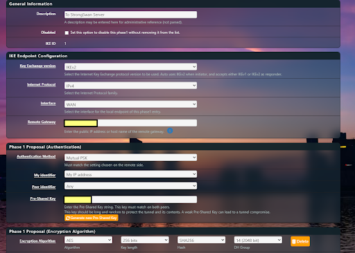
Fig 7: pfSense IPsec Phase 1 Configuration
Key Exchange: Select IKEv2.
Interface: Choose the internet-facing port.
Remote Gateway: Enter the hub’s public IP.
Authentication: Select Mutual PSK and enter the pre-shared key configured on the hub.
Encryption: Match the encryption algorithm used on the hub.
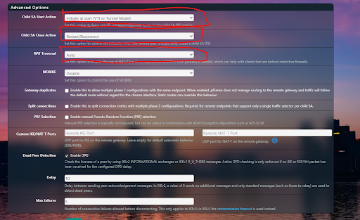
Fig 8: pfSense IPsec Phase 2 Configuration
Child SA Start Action: Set to Start – this lets the pfSense router initiate the tunnel, bypassing NAT limitations.
Child SA Close Action: Set to Reconnect – the tunnel will attempt to re-establish automatically if it disconnects.
NAT Traversal: Set to Auto if the site is behind NAT. This allows IPsec to automatically detect NAT and switch to UDP encapsulation (typically port 4500), ensuring the tunnel can be established and maintained without requiring inbound port forwarding or special ISP configuration.
Save the Phase 1 settings, then add a Child SA (IKE Phase 2).
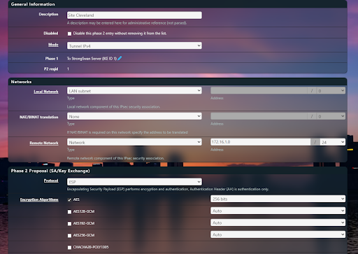
Fig 9: pfSense Child SA Configuration
Mode: Set to Tunnel IPv4.
Local Network: Enter the subnet you want the remote site to access.
Remote Network: Enter the subnet you want the local site to access.
Encryption & Hashing: Match the settings used on the hub/server.
Save the Phase 2 (Child SA) settings to apply the configuration.
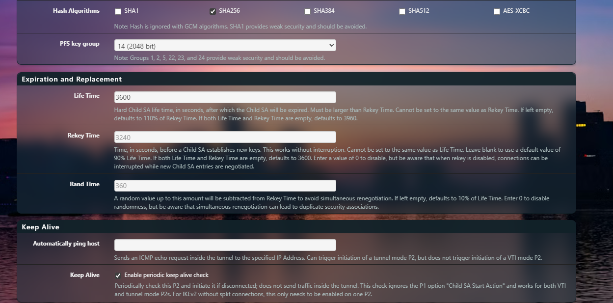
Fig 10: pfSense Child SA Configuration
Conclusion
By using a hub-and-spoke IPsec architecture with a publicly reachable StrongSwan hub, we were able to connect multiple NATed, dynamically addressed sites into a single routed network. This design avoided the common limitations of consumer ISPs and SOHO routers while still providing reliable inter-site connectivity and centralized control.
The combination of pfSense, OPNsense, and StrongSwan demonstrated that the solution was platform-agnostic and rooted in sound network design rather than vendor-specific features. Centralizing routing at the hub allowed us to scale to additional sites without the complexity of full mesh VPNs or dynamic routing protocols, making the environment easier to manage and troubleshoot.
While the hub introduces tradeoffs such as a single point of failure and potential throughput constraints, these limitations are well understood and can be mitigated through redundancy and resource scaling. Overall, this approach provided a practical, scalable solution for linking multiple home labs and remote networks, enabling larger distributed projects to function as if they were part of one cohesive environment.